Step 4 – Septic System
A solid plan to remove sewage from the home is required by my county and many others before they even give you a permit to start building your own home. My town doesn’t have a sewer system, so I not only require a plan to remove the sewage but also to treat it. Standard treatment of sewage hasn’t changed much over the years. Nature actually had it figured out pretty good before humans even attempted to manage it. Given enough time, soil and the organisms that inhabit it are extremely adept at breaking down harmful toxins and dispersing the safer compounds into underground waterways. The only thing a septic system does is harness nature’s awesome power. Designing a proper system starts with a soils test and/or “perc” test. A soils test involves removing a deep core of soil and analyzing what appears in the different layers. Soil is then classified into sand, gravel, loam, clay, and all sorts of combinations of those types.

A perc test involves filling a deep hole with water and timing how long it takes water to percolate through the soil at the bottom of the hole (the soil must be prepped by soaking it thoroughly first and most counties require you to have a license to complete the test). Both tests can give a pretty good indication of how well a particular patch of soil will perform at breaking down the “effluent”, which is what sewage becomes after sitting for a period of time.
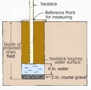
In my state, the soils test or perc test must be completed by a licensed septic designer. The designer I hired charged $150 and found my soil to be “sandy loam” for the top inch and “medium sand” for the next two feet until reaching the water table at 28″. This is the depth at which dry soil becomes saturated with water due to an underground spring. The county and state health codes dictate what kind of dispersal system can be used for a given type of soil, and for my great soil and water table depth they allowed me to use a gravity distributed system, which is the simplest type.
The next step in the design called for locating the area of the lot where the drain field would be located. Health codes dictate setbacks for the field of 5′ from property lines, 10′ from water lines, and 100′ from natural water supplies. I have a natural canal on one end of my property, and the 100′ setback took up a substantial amount of the lot. The drain field needed to be 400 square feet, and there also needed to be a reserve field of the same area set at least 6′ away from the main field. I had a problem here because it was impossible to fit both fields into the setbacks. Fortunately, by using the next system up from gravity I was able to use smaller fields that fit within the setbacks.

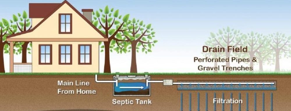
The type of design I will be installing is a pressure distributed system. It’s basically the same as a gravity type system but with the addition of a pump. This balances the distribution of effluent more evenly across the field and thus allows for a smaller area. The sewage from the house exits the main drain pipe and enters a 3 compartment concrete septic tank.

The first compartment is the gravity chamber, in which gravity separates the sewage into solids that sink to the bottom, a layer of fatty sludge on the top, and a cleaner liquid in the middle. The liquid in the middle is allowed to enter the second compartment, called the filter chamber. In order to exit this chamber, the sewage must decompose into small enough particles to pass through a filter. In the last compartment, the pump chamber, a water pump sits at the bottom. When the level of liquid in this chamber causes a float to reach a certain height, the pump turns on and pumps some of the liquid out of the tank and through a pipe to the drain field. There are two more floats, the first to ensure the pump doesn’t run too often and the second to sound an alarm if the pump isn’t working and the tank is getting full.

It’s a relatively simple operation, so I’m planning to get it all done in less than a week! In just two days from now, a local contractor with a backhoe will be coming out to dig a deep hole for the tank. I will check the depth as he digs and ensure it is correct. Around midday a crane will arrive and the tank manufacturer will drop it into the hole. We will immediately begin filling it with water while the backhoe gets started on digging the main field. It’s very important to get the drain field completely level and ensure that it is at precisely the correct depth. If you go too low there won’t be enough soil to break down the effluent and you can’t just add soil back in because then it will be classified differently. If you don’t go deep enough there won’t be enough soil to protect the effluent from the human activity above. The health inspector must pass off the installation of the design and he will pay very close attention to the depth of the field.

In the following days I will be assembling all the necessary pipes that lead to and from the tank, the floats that go inside the tank, and the pipes that will lie inside the field and distribute the effluent evenly across the entire area. These lines will be covered with large plastic tunnels called gravelless chambers. The last step will involve wiring the control panel to the floats and pump and hooking it up to power. My goal will be to get it all done within 5 days because that is the day the health inspector comes out. If I don’t finish I will have to wait another week! I was very pleased with the deal that the septic designer got for me. You can see the total cost of the system by clicking on the Project Budget link on the home page. He is also going to check up on me throughout the installation to ensure I’m getting everything hooked up correctly.
Advice? Questions? I'd love to hear your feedback or help you out in any way I can!