Step 19a – Plan Out the Ductwork
I meticulously planned out my electrical and plumbing runs before I even submitted my plans to get a building permit. Unfortunately I had not done likewise with my ductwork. I had planned for a conditioned space in the attic to house the ERV, but hadn’t really figured out how I was going to keep all of the ductwork in conditioned space as well. Installing the ducts in conditioned space reduces the cost of insulating them and makes the system work more efficiently. Most importantly, it removes any potential condensation issues from ruining the attic insulation. However, with my budget design using 8′ ceilings, there wasn’t a whole lot of headroom to be giving away to duct chases. I eventually settled on a design I believe will work out well without taking away too much headroom. That having said, if I had it to do over again I would have planned it out ahead of time. I also would have completed ductwork before electrical because wires are easy to work in and around pipes than the other way around. It is yet another entry in my list of things I have learned! The first step now in preparing to install the ERV system was to frame the conditioned space in the attic.
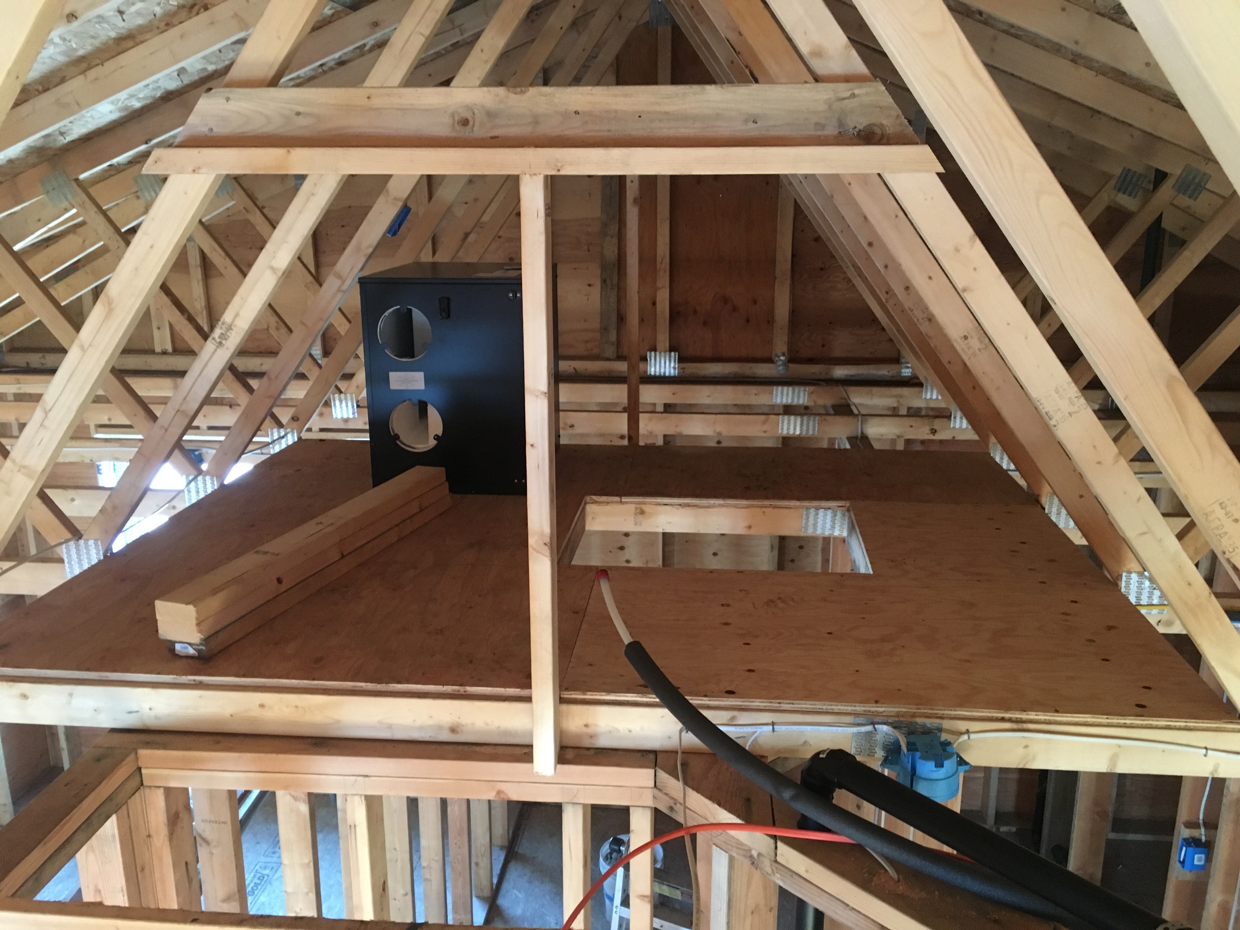
The key with attic framing is to maintain separation between the trusses and the top plates of the walls so that the framing doesn’t prevent the trusses from flexing. Trusses are designed to flex as they experience upward and downward forces due to wind and gravity. I attached some 3/4″ plywood to the bottom chord of the trusses and cut out a code minimum 22×30 opening for the access hatch. Keep in mind that any equipment you have in the attic must be able to fit through the access. The only reason I was able to use a code minimum access was because both the steamer and the ERV are able to fit through that size opening. (You can see the ERV above). I continued the framing by installing vertical members to support drywall. The truss chords will support the other two sides of drywall, which will run diagonally and form the trapezoidal attic space you can imagine from the pic above. You can also see below how I installed an electrical outlet for the ERV, and both an outlet and a hot water stub for the steamer.
Best practices for ERVs include exhausting air from bathrooms and kitchen, and supplying it to bedrooms and living rooms. I designed my system to exhaust from four locations, two downstairs and two upstairs. Downstairs exhaust grilles will be in the guest bathroom and the kitchen, and upstairs will be the master bathroom and the master water closet. I will likewise have four supplies, with two downstairs in the guest bedroom and dining room, and two upstairs in the master bedroom and living room. It is my hope that this setup will make for a very well balanced system.
Building codes call for 60 CFM (cubic feet of air per minute) to be ventilated continuously, but I wanted the option of a boost in the system so I went with a 200 CFM capable unit. Boost switches will be located in all four exhaust locations so that after using the toilet any nasty smells will be quickly exhausted, and if there is excess moisture in the air when cooking or showering that can be exhausted as well. The switches are very simple and similar to the one you see to the left with a button that signals the ERV to operate on boost for a set amount of time. The water closet will be set on a 5 minute boost, and the other exhausts will be set on a 15 minute boost.
The sizing of the ducts can be a very complicated task with a multitude of variables, but for my small, low power ERV I just followed the manufacturer’s suggestions. For larger systems, you can download software to perform Manual D calculations and size the ducts for you. Both supply and exhaust ducts will start at the ERV with a short 6″ diameter duct before splitting into two more 6″ ducts. Each of these four ducts will then split as well so there will be a total of eight 4″ ducts.
The next step was to frame the chases for the ducts. For those not in the know, a chase is a walled off space for piping or ducts. Framing a chase is no different than framing a wall. You measure out the length you need and cut a matching bottom plate and top plate, and then nail miniature studs between them. The chase is then nailed to the top plates, and miniature joists are nailed between the bottom plate of the chase and the studs of the wall. I used mostly spare lumber I had leftover to frame all the chases so it is a really good way to use up scrap pieces and save sustainably.
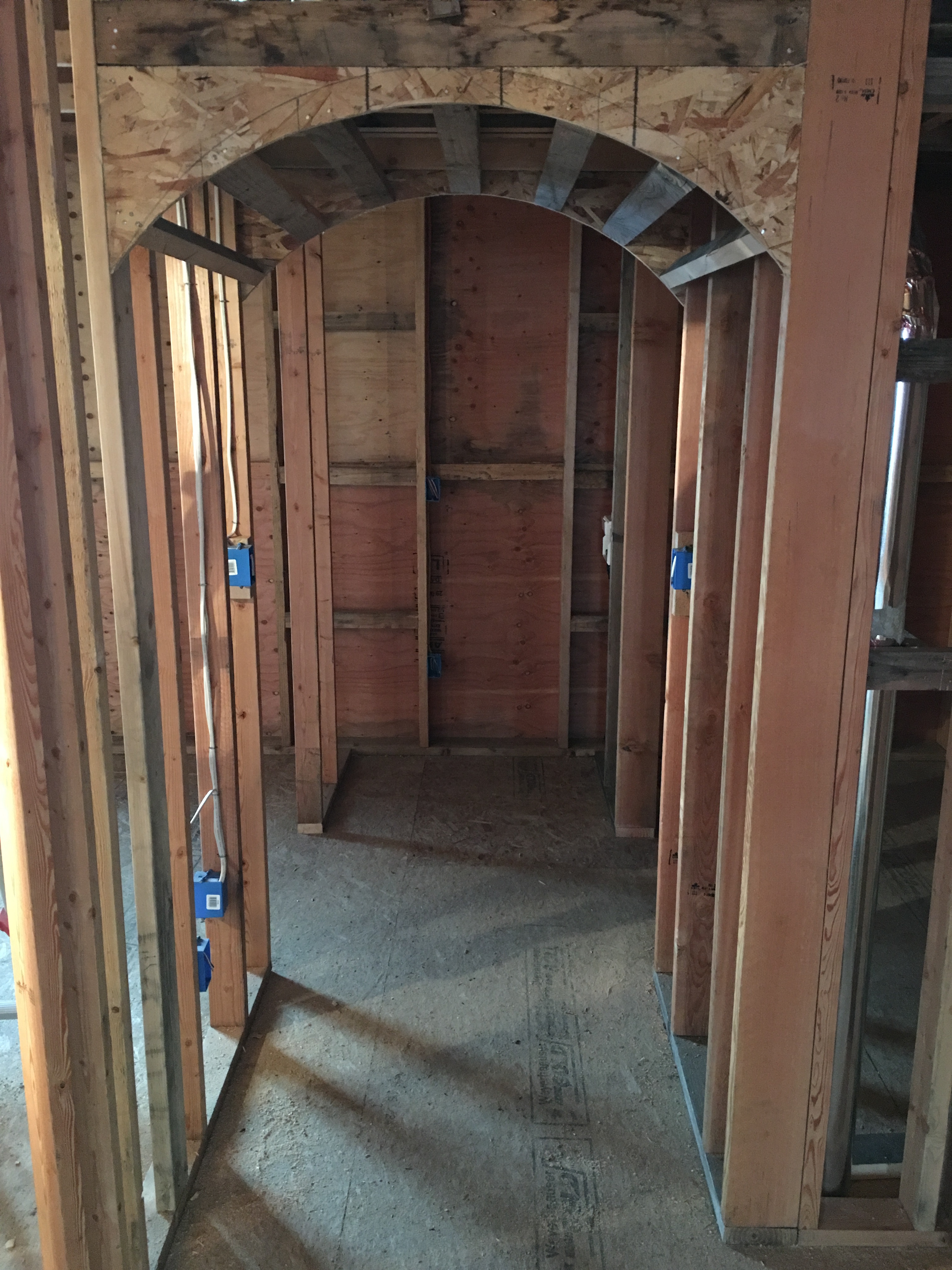
I decided to add an arch to several of the chases as well. I’m hoping that the esthetics of the arch will take away from the fact that I had to take off a foot of head space to make room for the chase. Luckily, this only happens in the part of the house between the master bathroom and master closets so I’m hopeful that the headroom will not be missed. An arch is actually quite simple to frame, and is very much like the curved wall that I framed on the second story of the house. All you do is use a pencil and string as a compass to make a curved line on plywood and then cut it out so the arch is left. You repeat this process on a second sheet of plywood for the other side and then nail small 2×4 blocking between the two. I was really happy with the way it turned out!


Advice? Questions? I'd love to hear your feedback or help you out in any way I can!