Step 4b – Inside the Tank!

Today I almost completed the septic install but am waiting on a couple more parts. For the second time already in my build I underestimated the amount of wire I needed and now I’m stuck with a couple pieces that are too short and need to return to the electrical store to get longer pieces. An important part of successfully building your own home is knowing where your deficiencies are and I tend to cut things just a little too close due to not wanting to waste anything. With wire, hopefully this will be the last time I underestimate the length I need!

I began the day by running 1.5″ PVC from the tank to the drain field. I learned a lot from the mistakes I made running electrical conduit since the white PVC for the septic is assembled and glued the same way as the grey PVC for the electrical. The end result was a well planned and perfectly aligned run. The next step was attaching the float switches inside the pump chamber of the septic tank. There are three floats that will work together to operate the pump. The float switches are bell shaped plastic parts attached to low voltage cords. They are very simple but ingeniously designed. When the water is low, gravity pulls the float down so the heavier bell end is down. When the water level raises, the bell end floats upward, causing a sliding metal part inside the float to meet another metal part in the middle and complete the circuit. The design was very specific on the placement of the floats on the PVC pole.

You can’t see them very well in the pic at the top of the page, but if you follow the white PVC pole that extends from the top of the tank down to the bottom on the right side of the pic, you will see three black objects attached to the pole at different heights. The first float was to be placed 13 inches from the bottom of the tank. This switch controls the ‘redundant off’ function in the control panel. Basically it ensures that the pump continues to run until the effluent level is low enough to lower the float. Without it, the pump would wear out a lot quicker because it would run so often. Imagine if you took out the garbage to the street every time you had a piece of trash! It’s much more efficient to have a small container and only empty it when the container is full.
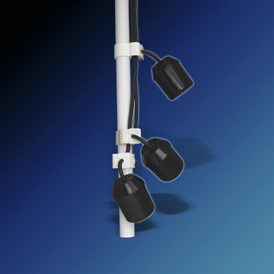
The second float is placed 20 inches from the bottom of the tank. Once the effluent level is high enough to raise this float, the pump activates and continues to run every six hours until the “redundant off” float is lowered. The third float is the high level switch, and is placed 35 inches from the bottom of the tank. This activates an alarm and a siren if the float is raised. This allows the owner sufficient time to figure out what is wrong and fix it before the effluent level gets so high that the tank overflows. As you can see in the photo, the floats have cords that I coiled up and then ran into a grey junction box. Inside the box, I spliced the wires with another set of wires coming from the control panel. By NEC code, you must use special silicon wire nuts to splice them to protect against the corrosive sewer gases that will soon occupy the tank (this is most likely overkill because the junction box is air and watertight. You can also see in the pic the the white rope that I can use to pull it up the pump if I ever need to perform maintenance on it (much better than diving in).

You can see how I’ve mounted the control panel on a 2×6 pressure treated post and run wires through 3/4″ conduit from the panel down towards the pump chamber riser. Tomorrow I will buy a rubber grommet to make a seal as I drill a hole through the side of the riser and run the conduit into the junction box. The last step will be running some 12/2 UF cable from my temporary power pole underground to the control panel. If you look carefully you can see the 1.25″ connector at the bottom of the control panel where another conduit will run into the panel with power.
The other part I will get tomorrow is the flexible hose assembly that will connect the pump to the 1.5″ PVC I talked about in the beginning of this post. In the sample pic above it is the hose attached to the red pump on the right side. Once that is hooked up it’s just a matter of filling the tank with water and checking to ensure everything is working properly. In 4 days, the inspector will come and check for himself that everything is functioning properly and then I will be able to connect my trailer sewer to the septic inlet and start using it! The backhoe operator will return and cover everything back up with dirt so the tops of the inspection ports are just barely visible.
I have the same setup but haven’t installed my effluent pump yet. You didn’t mention any weep hole in the discharge pipe? I see some discussions where a small weep hole is added below the check valve to avoid air-locking the pump.
What pump size did you use? 1/3 or 1/2 hp? I assume you forgot the pump controller in the budget sheet. Only the $235 pump is mentioned (you didn’t get pump and controller for that, did you )?
I’ll have to ask the septic designer about the weep hole. That’s interesting. I actually have a 0.4 HP pump so you were pretty much right. The control panel is listed towards the bottom at $487.