Step 17b – Wiring Lighting Circuits
Lighting circuits are by far the hardest ones to wire. Modern LED lights use very little power, so I only used two lighting circuits for the entire house. One powers the first story lighting, and the other takes care of the second story. There are multiple ways to wire lights, and I will go over several of them, but the important thing to keep in mind is that every light needs power from the panel, and every light needs to be wired to a switch. Sometimes it is easier to bring power to the switch, and then run a wire from the switch to the light, as you can see below. We can follow the electricity as it enters at the bottom of the picture on the black (hot) wire. The electricity travels to the  switch, and if it is activated, continues on the other black wire to the light bulb. After powering the light bulb, the electricity travels back through the white wires to the main panel. (Although this makes explaining things easier, keep in mind that electricity doesn’t really work this way. I will spare you the detailed explanation but it might be helpful to think of water as an analogy. If we have a water pump connected to a pipe connected to a water wheel, we wouldn’t follow an individual drop of water as it starts at the pump and goes to the water wheel, we would just see that the pump would apply a force to the water and that force would move the water wheel)
Now, you might ask, what about the ground wires? You must be wondering, if electricity doesn’t pass through those wires then why are they even there? This is a great question. Ground wires are only used in emergencies, and are part of the grounding system of the house to protect people from being shocked. Let’s say that somehow the “hot” 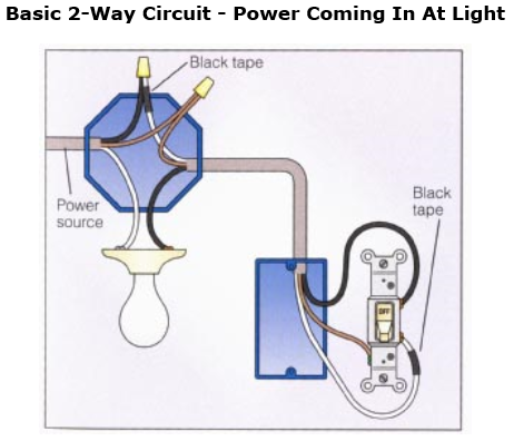 wire becomes loose or corroded over time, and comes into contact with part of the light fixture. That fixture is now electrically charged so if you touch it, you could get electrocuted. Fortunately, the ground wire is also connected to the light fixture, and also connected to the ground, so the current will flow through the ground wire to the ground. Building codes require the path of the grounding wires to encounter very little resistance, so with a little knowledge of Ohm’s Law which I won’t bore you with at the moment, you would know that this low resistance will cause the current to spike and trip the breaker, cutting power off to the circuit.
Alternatively, the power can be brought first to the light, and then to the switch. This gets just a little bit more complicated due to the wire coloring. We can once again follow the electricity as it comes in on the black wire, and then…. goes to a white wire, with black tape? Romex comes with one white and one black wire but in this case we needed two black wires, one for power from the switch to the light and one to take power to the switch, so the white wire must be marked as black using some electrical tape. This is for safety reasons so that anyone working on the electrical components will know that both of the wires are potentially “hot”.

Both ways work perfectly fine, but as you wire a house you will quickly find that in certain situations one way will be much easier than the other. Sometimes, it will be easiest to run power to a switch, and then wire that switch to a light, but you will have another switch that you want to run power to that is near that light. Rather than run a second wire from the first switch to bring power to the second switch, you can simply use a 3 conductor wire from the first switch to the light, and then run a regular two conductor wire from the light to the second switch. The first two conductors bring power through the first switch to operate the light, while the third conductor brings unswitched power to the second switch. It can get quite confusing if you don’t really think things out as you go.
Another time when you need to use three conductor wire is when you connect a light to multiple switches. This is required by building code when you wire a light over a stairway so you can operate the same light from either the top or the bottom of the stairway. The third conductor is wired between the two switches so that the light can be powered through one conductor if both switches are up, or through the other conductor if both switches are down. If one switch is up and the other is down the circuit is disconnected and the light will not be lit.

In the master bedroom, the main light can be operated via a switch at the entrance, or alternatively via switches at either side of the bed. In effect, three different switches are capable of operating the same light! This is called a 4 way switch and you can get the idea of how it works similarly to the 3 way. The middle switch will run power either parallel or in a cross fashion as in the pic.
 For the light fixtures, you can use wall boxes for sconces or octagonal junction boxes for hanging fixtures. There are reinforced boxes you can use that are capable of handling heavy chandeliers as well. Just as with the gang boxes, it is important to do box fill calculations to ensure that the box you are using has enough room for the amount of conductors you wish to pass through it (here you can see this junction box allows twelve 14 gauge conductors, ten 12 gauge, and nine 10 gauge).
Advice? Questions? I'd love to hear your feedback or help you out in any way I can!